SubjectSAMUEL I. BURNS
DisciplineMECHANICAL ENG.
InstitutionUSC · LOS ANGELES
Class of2027
UTC—

SAM·BURNSengineer

// MECHANICAL ENGINEERING STUDENT @ USC
// INCOMING AVIONICS MECH. ENG. INTERN @ SPACEX
// MAY 2027 GRAD · GPA 0.00/4.00

REV. 05 · 15.OCT.2026SHEET 01 OF 09SCALE 1:1
↓ SCROLL
⊕ DATUM 01 · X=0 Y=0

experience.

CO.01

SpaceX

Incoming Avionics Mech. Eng. Intern · Starship Electronics
JUNE 2027·HAWTHORNE, CA
CO.02

Joby Aviation

Mechanical Eng. Intern / Part-Time Mechanical Eng.
SEP 2025 — OCT 2026·SANTA CRUZ, CA
CO.03

8VC

Summer Fellow
SUMMER 2026·SAN FRANCISCO, CA
CO.04

nTop

Modeling & Automation Intern
MAY — AUG 2025·NEW YORK, NY
CO.05

Terra Labs

Project Manager / Mechanical Engineer · COVE Arm
2026 — PRESENT·LOS ANGELES, CA
CO.06

USC Viterbi

B.S. Mechanical Engineering
2023 — 2027·LOS ANGELES, CA

Passive magnetic bearing · 3U CubeSat reaction wheel test rig

ROLELEAD MECHANICAL DESIGNER
ORGAME 441AL · USC
TEAM4 ENGINEERS
PERIODAUG 2026 — PRESENT

A passive magnetic bearing for a CubeSat reaction wheel, and the 40-part rig built to test it.

0PARTS IN THE RIG
0CUSTOM PARTS, GD&T DRAWN
0.00mmSTACK-UP FITS
0µmFLYWHEEL ECCENTRICITY BUDGET
0.01N·m·sWHEEL MOMENTUM
0DRAWING REVISIONS
  1. 01
    SIZING

    C360 brass flywheel sized from first principles to slew a 3U CubeSat 90° in 10 s: 0.01 N·m·s, matching Rocket Lab's flight RW-0.01.

  2. 02
    STRUCTURE

    Nonmagnetic 6061 on a reconfigurable 80/20 frame, with 3D-printed fixtures. The camera tracks the rotor's orbit; a reaction torque sensor reads torque across the bearing.

  3. 03
    MODULARITY

    2, 3 and 4 mm air-gap tests by single-part swap: three magnet journals share one rotor shaft, flywheel and housing.

  4. 04
    CAD + GD&T

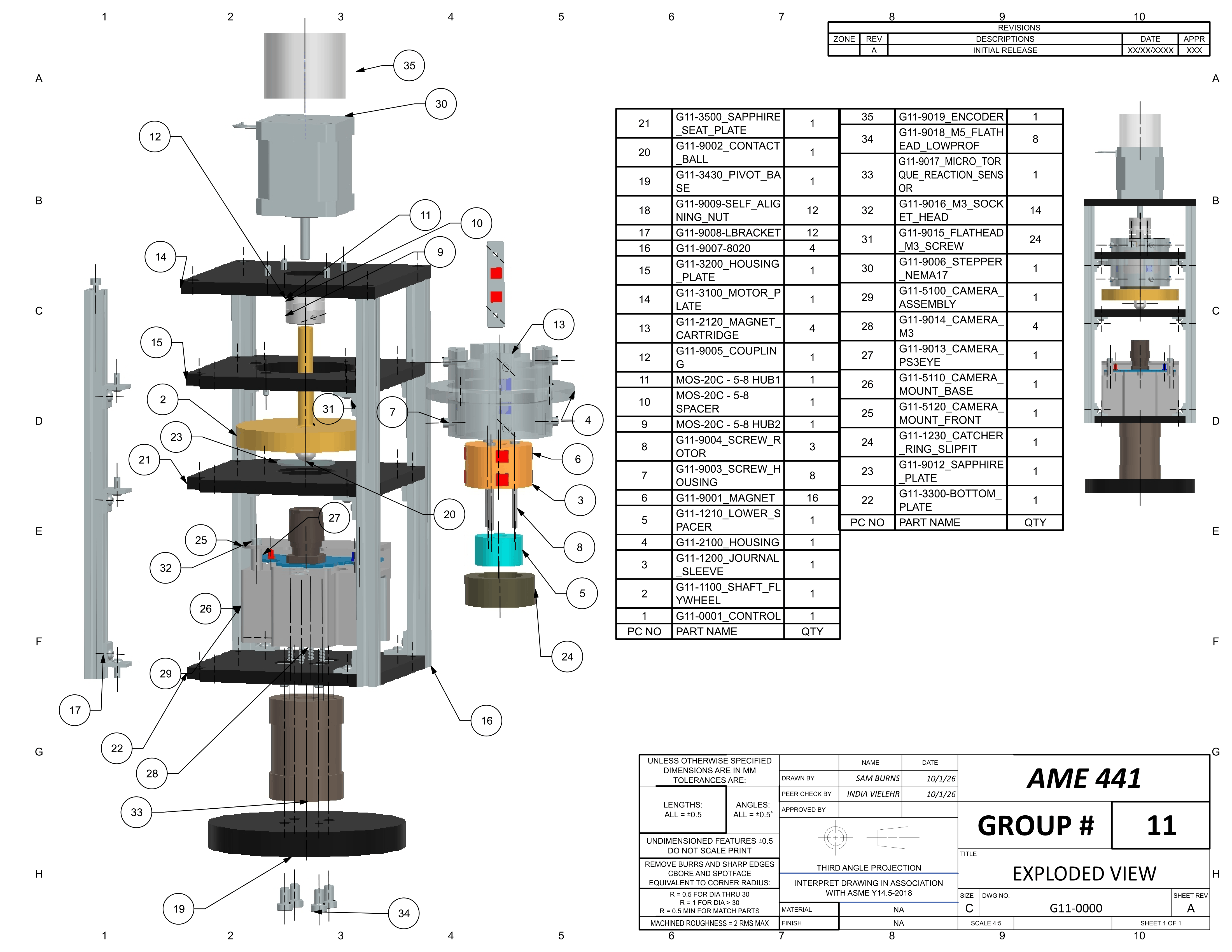
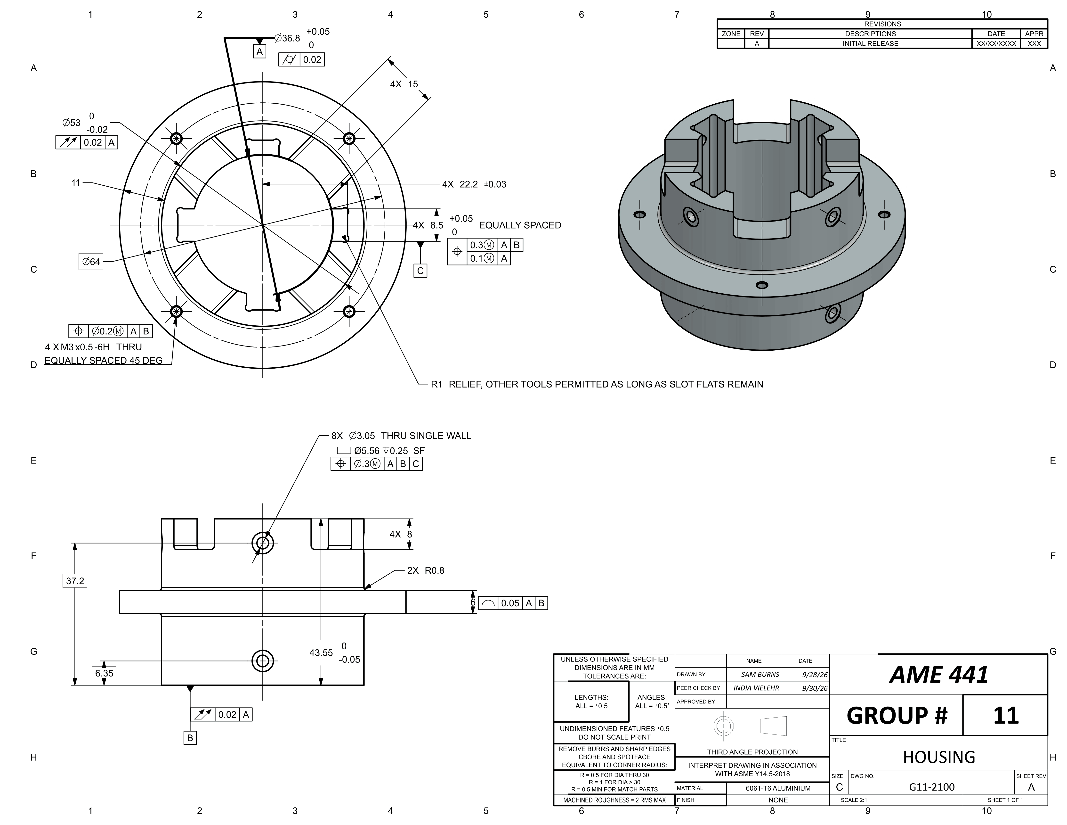
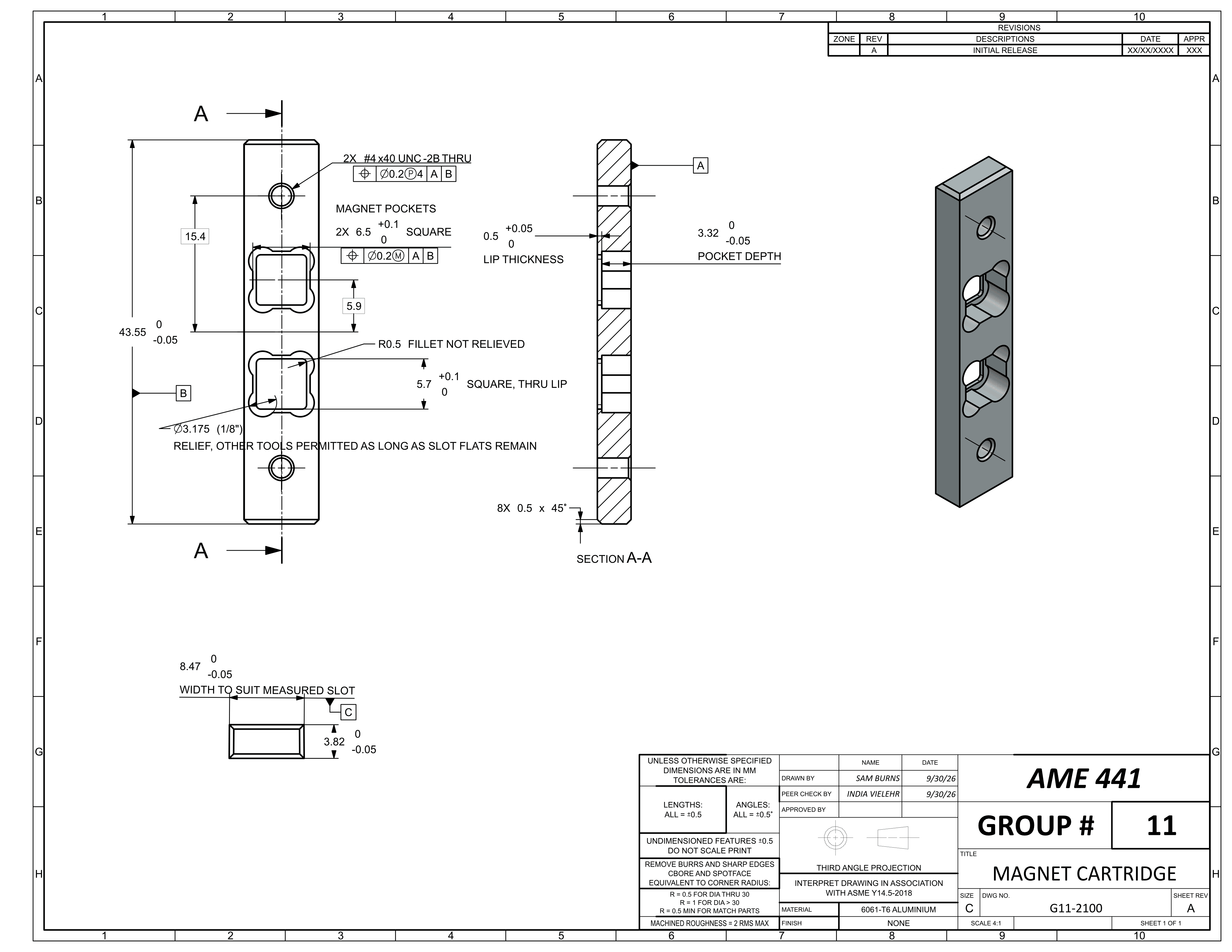
    15-parameter Siemens NX model and 11 ASME Y14.5-2018 drawings, datum frames and position tolerances matched to COTS drawings.

  5. 05
    DFM

    Tooling and setup notes worked into the drawings with USC's machinist. All 11 CNC-turned and 4-axis-milled parts made first pass.

Siemens NXGD&T · ASME Y14.5Tolerance stack-upsDFMCNC turning4-axis milling80/203D printing
// DRAWINGS
// BUILD
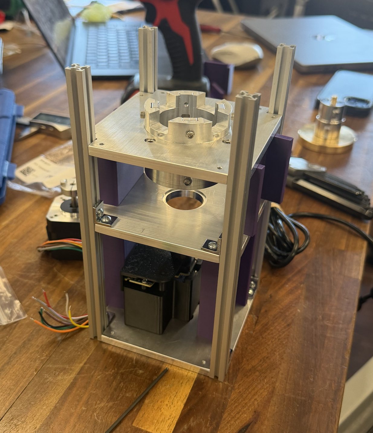
Assembled test rig: 80/20 frame, aluminum plates, housing and motorRIG.01
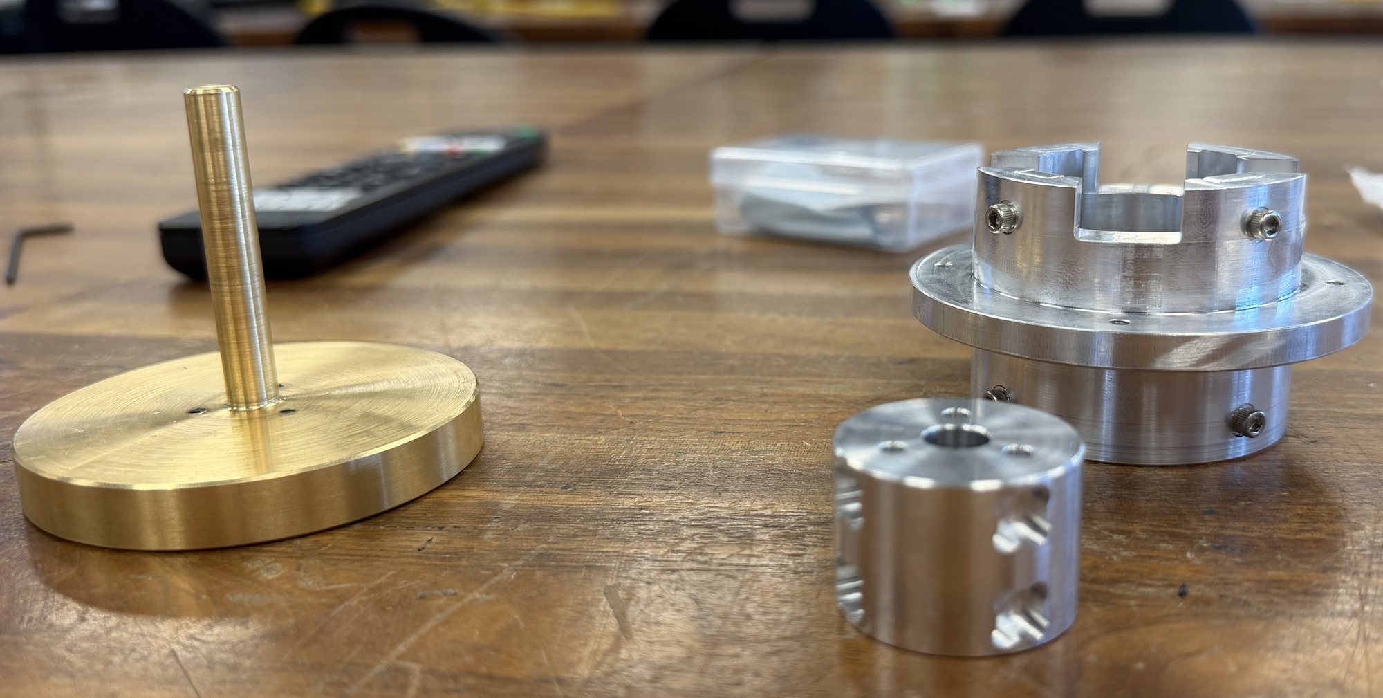
Machined brass flywheel and shaft, aluminum housing and magnet journalMACH.01
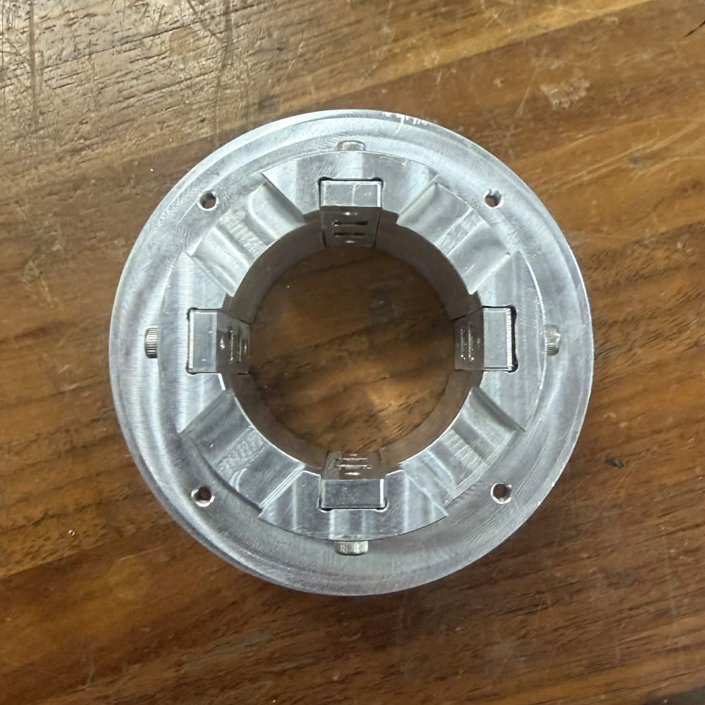
Housing from above with the four magnet cartridges installedMACH.02
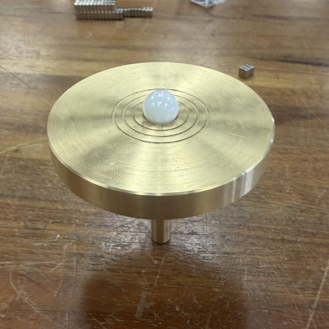
Brass flywheel with the zirconia contact ballMACH.03

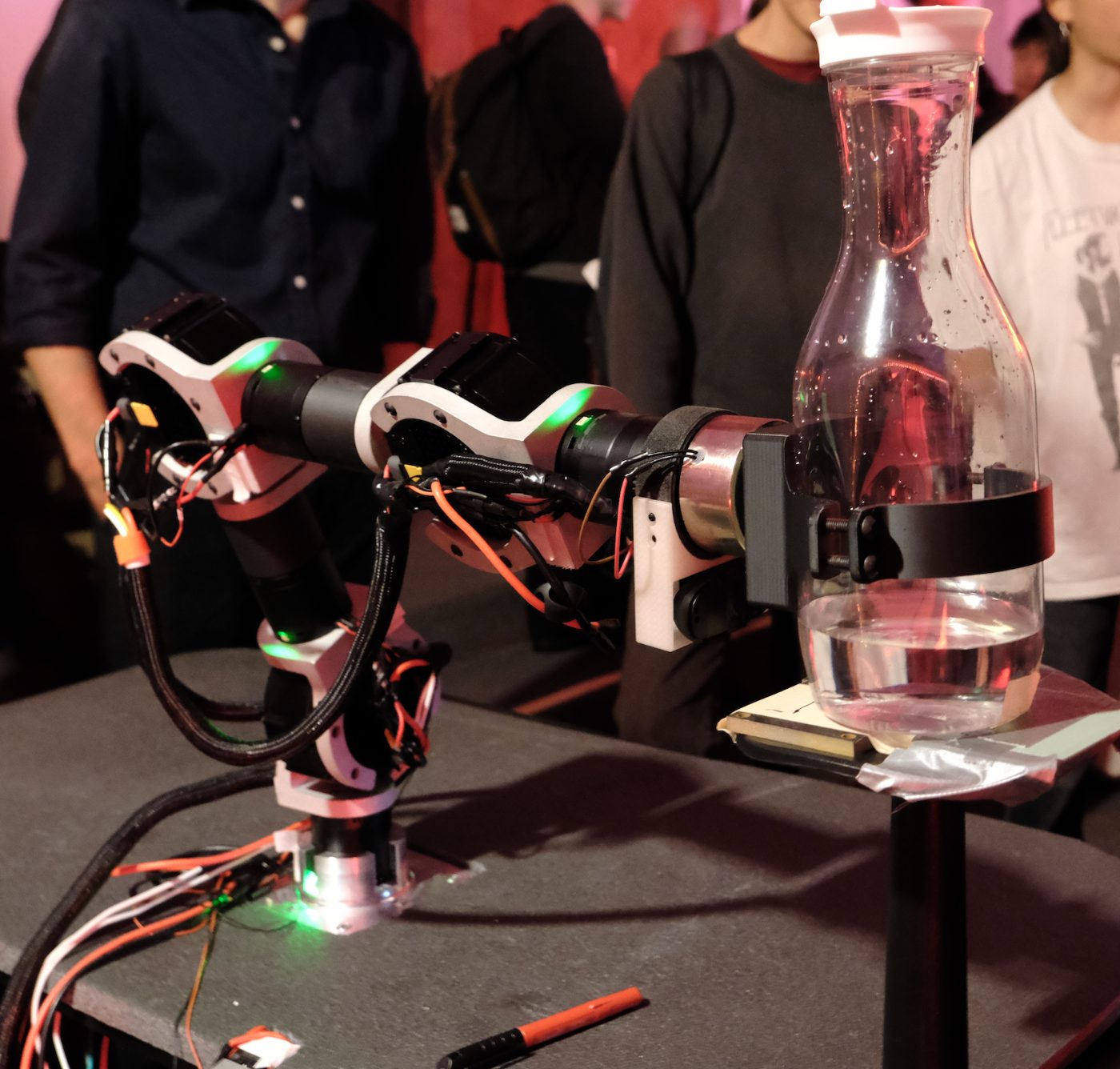
Terra Labs · COVE 7-DOF robotic arm

ROLEPROJECT MANAGER / MECH. ENGINEER
ORGTERRA LABS · USC
PERIODFEB 2026 — PRESENT
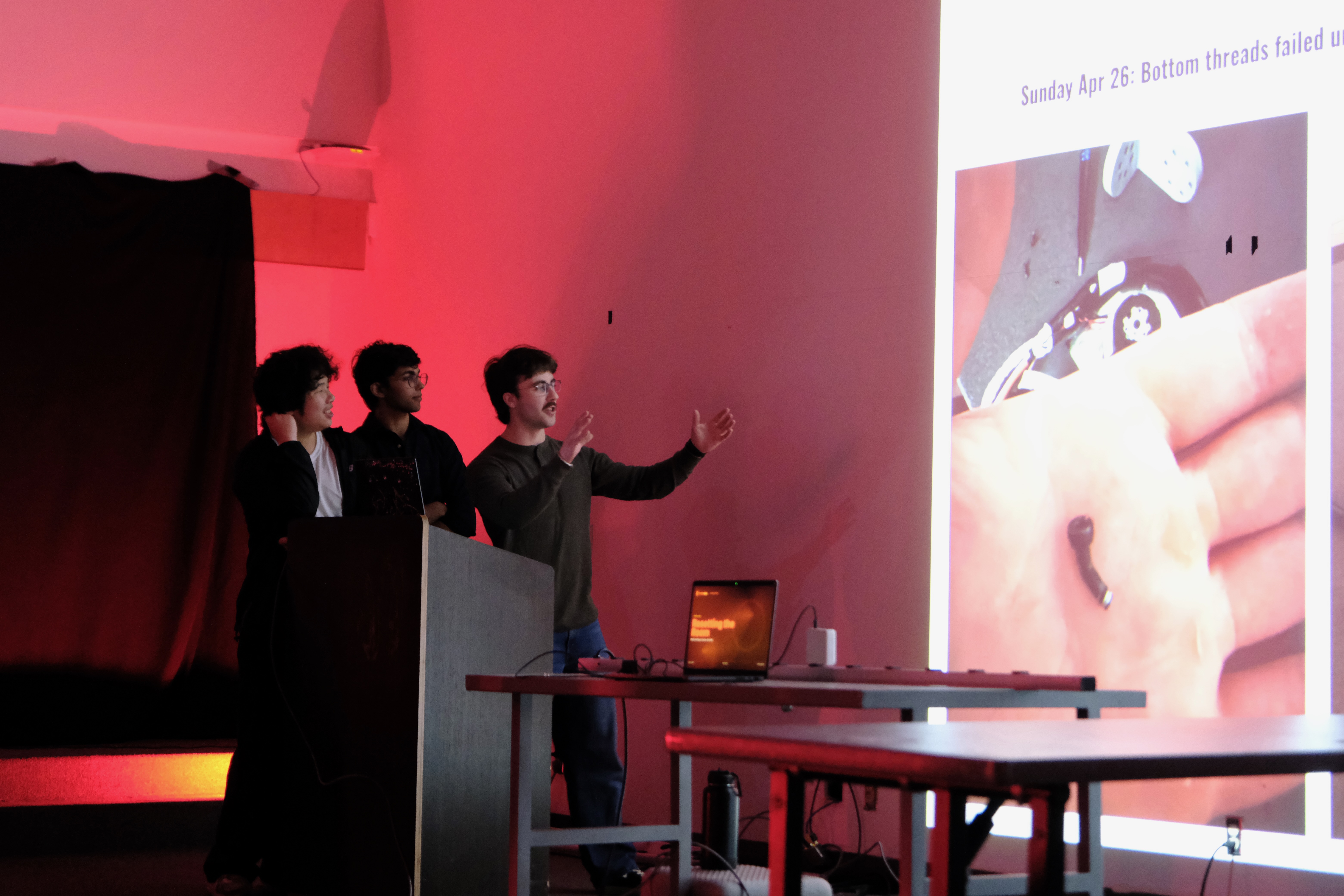
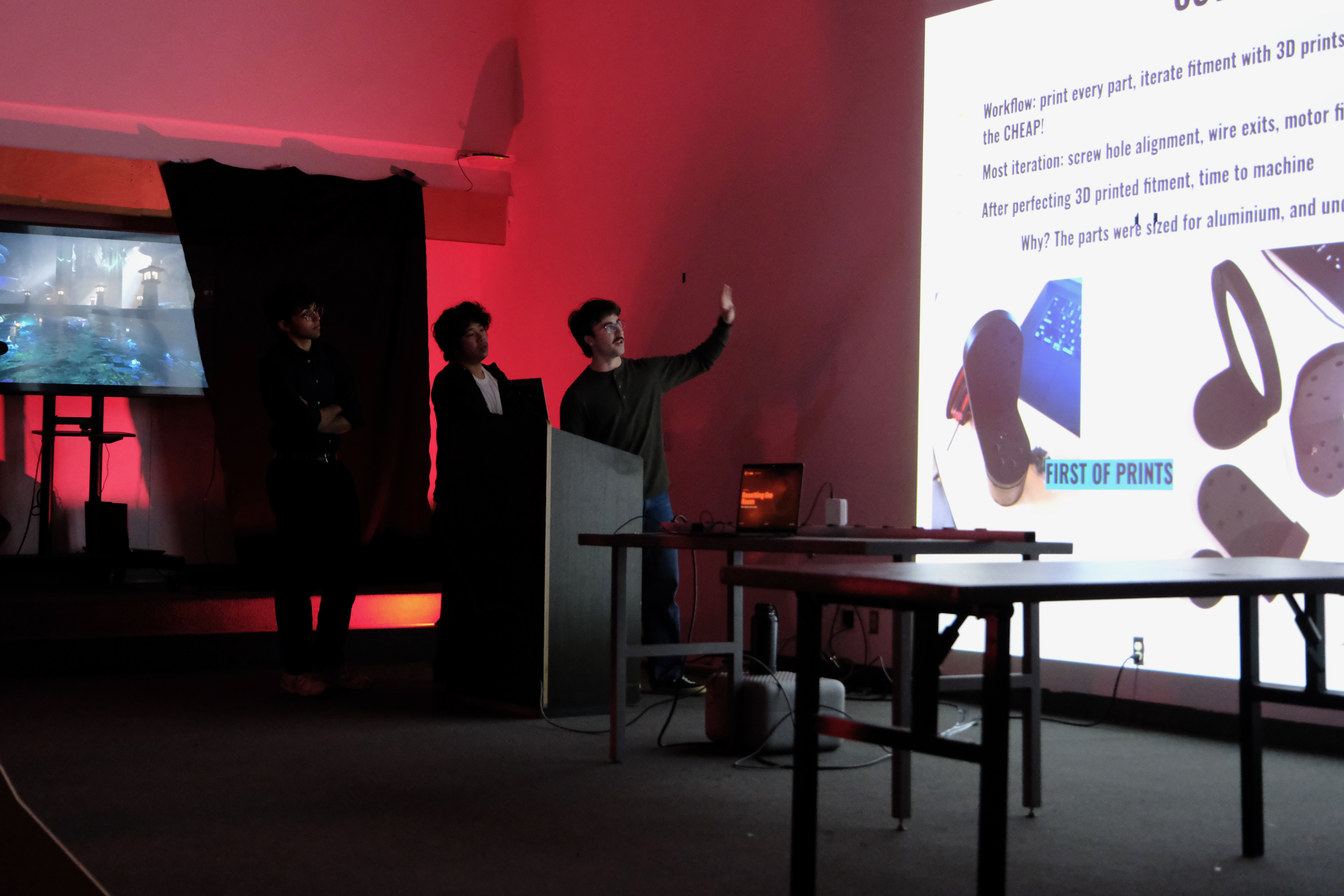
presentationPRES.01
presentationPRES.02
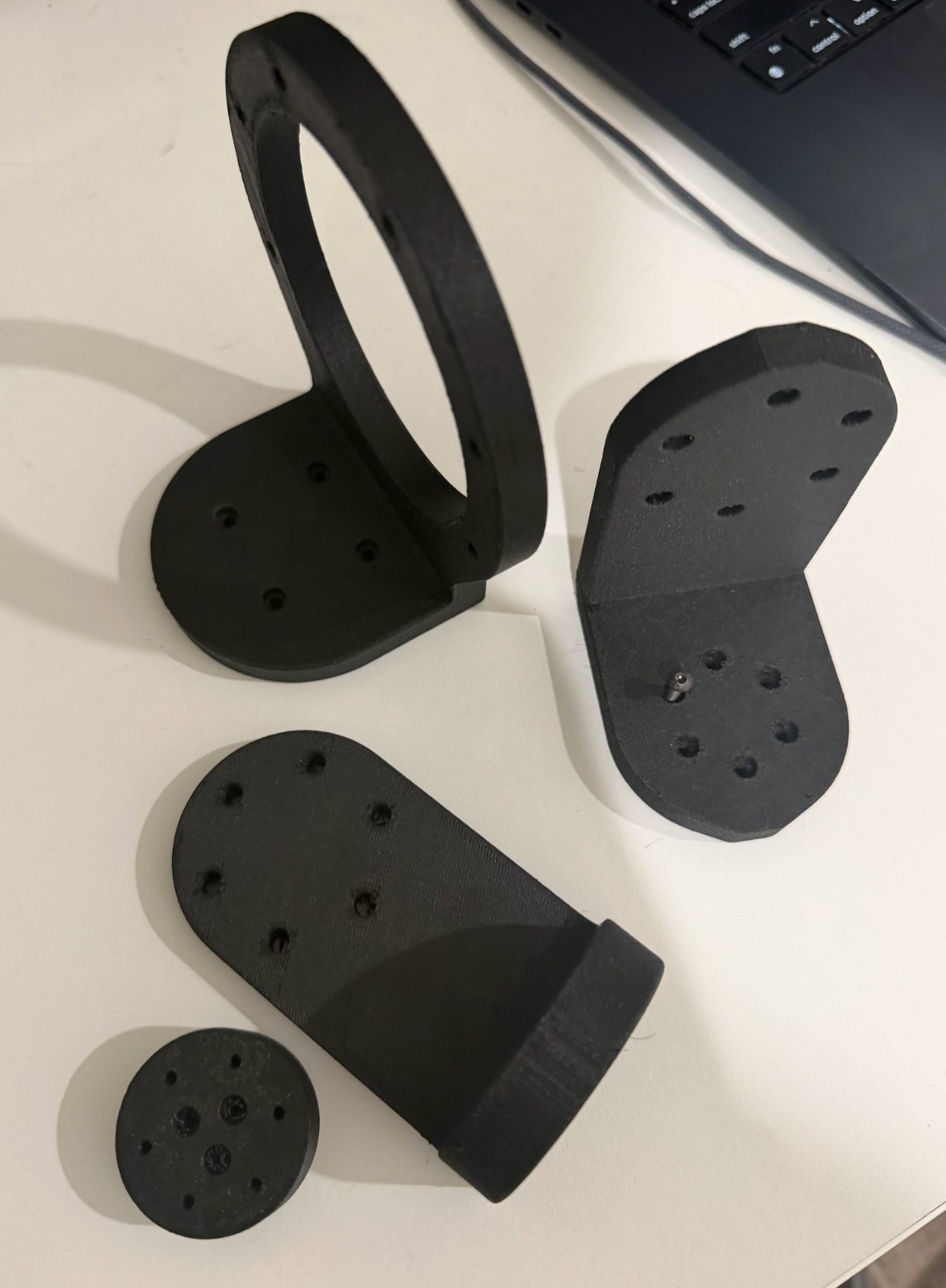
first printsPROTO.01
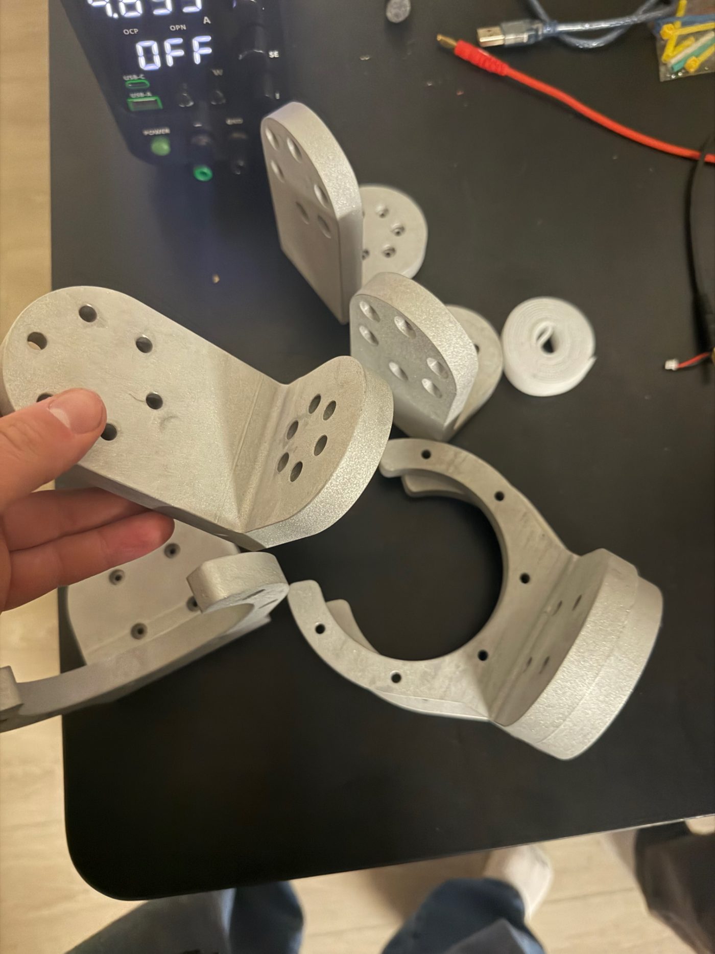
machined partsMACH.01
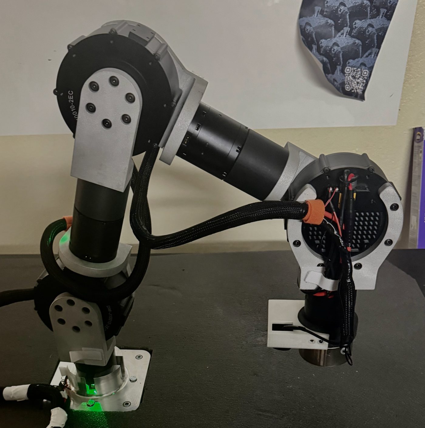
finished armBUILD.01
load demoTEST.01
// PHOTOS
ASSEMBLY0/128
01 / 128
LIVE DEMO0/128
01 / 128

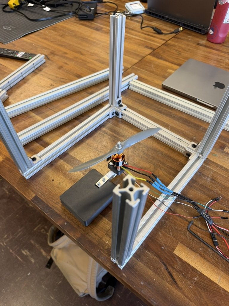
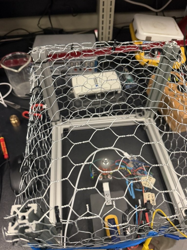
Custom 10N Thrust Stand.

ROLEDESIGN + BUILD
ORGAME 341B · USC
PERIODAUG — DEC 2025
FRAME 01 / 128
↕ SCROLL TO ANIMATEPROGRESS · 0%
STG.01 · ACTIVE

mechanical design

custom CAD adapters for motor/load-cell and load-cell/base. table-clamped cantilevered thrust stand around a 1 kg binocular beam load cell.

  1. STG.01mechanical design
  2. STG.02electronics integration
  3. STG.03calibration + procedure
  4. STG.04characterization
  5. STG.05analysis
// PROCESS · 06 FRAMES
CAD assembly — custom adapters, motor mount, sensor housing.
01 CAD assembly — custom adapters, motor mount, sensor housing.
electronics schematic — HX711 / Arduino / ESC / BLDC.
02 electronics schematic — HX711 / Arduino / ESC / BLDC.
C_T vs RPM — experimental vs UIUC literature.
03 C_T vs RPM — experimental vs UIUC literature.
C_P vs RPM — both propellers.
04 C_P vs RPM — both propellers.
thrust vs RPM and thrust vs electrical power.
05 thrust vs RPM and thrust vs electrical power.
figure of merit — 9×6 wins below 3000 RPM; 9×4 above.
06 figure of merit — 9×6 wins below 3000 RPM; 9×4 above.

photos.

AVI.01
AVI.02
AVI.03
TRV.01
TRV.02
TRV.03
TRV.04
ARC.01
AVI.01
AVI.02
AVI.03
TRV.01
TRV.02
TRV.03
TRV.04
ARC.01
SPT.01
FOOD.01
FRN.01
FRN.02
ARC.02
TRV.02
AVI.04
TRV.05
SPT.01
FOOD.01
FRN.01
FRN.02
ARC.02
TRV.02
AVI.04
TRV.05

contact info .